
Sensory/Actuation Systems in Agricultural Vehicles [Professional]
Paper Introduction
The automation of agricultural tasks has received an important stimulus, especially in the area of selective weed control where high precision is essential for the proper use of resources and the implementation of more efficient treatments. Autonomous agricultural systems incorporate and integrate perception systems for acquiring information from the environment, decision-making systems for interpreting and analyzing such information, and actuation systems that are responsible for performing the agricultural operations. These systems consist of different sensors, actuators, and computers that work synchronously in a specific architecture for the intended purpose. The main contribution of this paper is the selection, arrangement, integration, and synchronization of these systems to form a whole autonomous vehicle for agricultural applications. This type of vehicle has attracted growing interest, not only for researchers but also for manufacturers and farmers. The experimental results demonstrate the success and performance of the integrated system in guidance and weed control tasks in a maize field, indicating its utility and efficiency. The whole system is sufficiently flexible for use in other agricultural tasks with little effort and is another important contribution in the field of autonomous agricultural vehicles. [1]
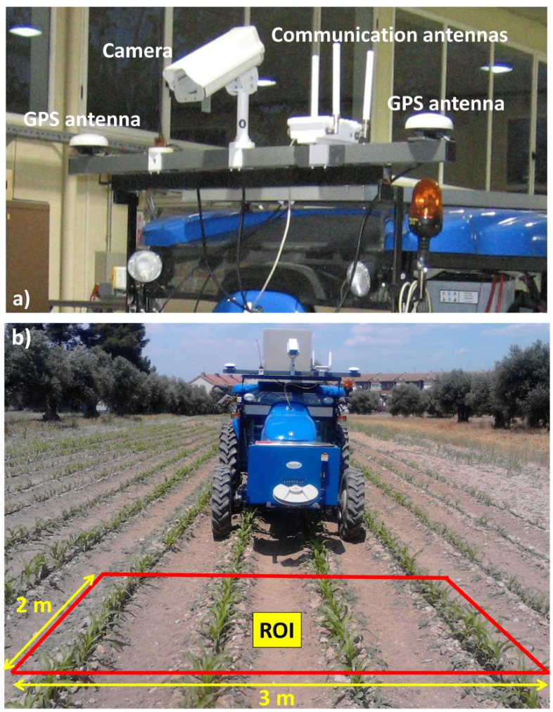
The perception system consists of three main sensors: color camera, Inertial Measurement Unit (IMU), and RTK-GPS (consisting of two antennas: one for XYZ positioning and the other for heading calculations). Figure 2 displays the main sensors on-board the vehicle based on a commercial tractor chassis. The camera and IMU are embedded into a housing with a fan controlled by a thermostat for cooling purposes, assuming that some agricultural tasks are conducted under high working temperatures, above 50 °C. The housing is IP65 protected to work in harsh environments (exposure to dust, drops of liquid from sprayers, etc.). Additional to the appointed sensors, the perception system also comprises a wireless communication device, to enable the user for remotely controlling and monitoring the entire system.

The camera-based sensor is the SVS4050CFLGEA model from SVS-VISTEK and is built with the CCD Kodak KAI 04050M/C sensor with a GR Bayer color filter; its resolution is 2,336 by 1,752 pixels with a 5.5 by 5.5 μm pixel size. This camera is Gigabit Ethernet compliant connected to the Main Controller. The IMU, of LORD MicroStrain® Sensing Systems (Williston, VT, USA) is a 3DM-GX3®-35 high-performance model miniature Attitude Heading Reference System (AHRS) with GPS. It is connected via RS232 to the Main Controller and provides information about pitch and roll angles. Both the camera and IMU are robust enough and exhibit sufficient capabilities for real-time performance, required for agricultural tasks. The GPS receiver is the Trimble® BX982 GNSS receiver, supporting two antennas for precise heading calculation, mounted on the lateral ends of the vehicle. The goal is to apply specific treatments in the Region of Interest (ROI) in front of the tractor, which is a rectangular area 3 m wide and 2 m long. It covers four crop rows in the field. This area starts at 3 m with respect to a virtual vertical axis traversing the center of the image plane in the camera, i.e., where the scene is imaged.
Figure 3, displays the camera system geometry. OXYZ is the reference frame located in the ground with its axes oriented as displayed, aligned with the reference axis of the GPS system; h is the height from O to the origin o of the reference frame oxyz attached to the camera; roll (θ), pitch (α), and yaw (β) define the three degrees of freedom of the image plane with respect to the referential system; d is the distance from the beginning of the ROI measured perpendicular to X axis.

Characteristics of the Perception System
Four properties have been identified as basic requirements for the perception system integrated into the proposed architectural design:
- Flexibility/ModularityThe perception system consists of the elements described above with a direct communication link to the Decision-Making System running on the Main Controller. Different sensors can be connected via GigaEthernet and RS232 communication ports, which are standard interfaces. Any sensor can be connected/disconnected without restrictions other than the physical capacity of the Main Controller. The operations of linkage and decoupling can be carried out via software, without affecting the remaining modules or the operability. This procedure allows a multi-sensor arrangement according to the required agricultural tasks. Some crop line detection algorithms do not need the IMU, and when this happens, this sensor is simply ignored and then activated when required. This method avoids important disruptions to the designed systems and at the same time proves the flexibility and modularity of the proposed architecture.
- ScalabilitySensors and their corresponding drivers can be added to increase the amount of work according to the demanded agricultural tasks. Again, the unique restriction is the limitation of the number of ports available in the Main Controller, which can be easily expanded. So, we could add a multispectral or thermal camera for plant discrimination or a stereoscopic vision-based system with a GigaEthernet connection for object detection for safety purposes. Different cameras with higher resolutions are accepted when required. Regarding the processing of data provided by the sensors, the Decision-Making System implemented in the Main Controller allows for high-performance processing.
- RobustnessThe camera-based system is robust enough to support the adverse outdoor agricultural environments with sufficient physical and electronic protections. It is designed to withstand mechanical vibrations from the tractor’s engine, soil roughness, extreme temperatures, and high variability in illumination. Additionally, the camera is equipped with an UV/IR filter to cut spectral ultraviolet and infrared radiation, which considerably affects the image quality. The IMU is encapsulated and calibrated to provide stable values.
- Real-Time/PerformanceThe perception system, particularly the camera, is arranged onboard the tractor to cover the region of interest where the specific actuation is to be applied. It is placed closed to the center of gravity to minimize vibrations and undesired mechanical effects. The image acquisition is controlled through the exposure time, again with the aim of achieving high quality images. The data processing for crop/weed detection and guidance is designed under specific modules, programmed as dynamic-link libraries (DLL) in C++, and embedded in the Main Controller. The modules are optimized to work in real-time for the proposed specific treatment.
References
[1] Luis Emmi, Mariano Gonzalez-de-Soto, Gonzalo Pajares, Pablo Gonzalez-de-Santos (2014) Integrating Sensory/Actuation Systems in Agricultural Vehicles. Sensors 2014, 14(3), 4014-4049; https://doi.org/10.3390/s140304014